
- #USING COMMON CATHODE LED WITH COMMON ADONE OUTPUT DRIVER#
- #USING COMMON CATHODE LED WITH COMMON ADONE OUTPUT FULL#
- #USING COMMON CATHODE LED WITH COMMON ADONE OUTPUT SERIES#
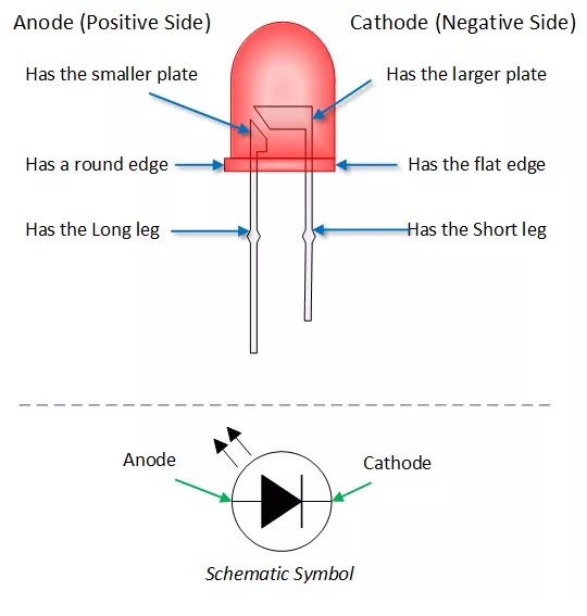
The 10K potentiometer is connected to the analog input AO, as indicated in the hookup diagram. D13 of the Arduino is reserved for the decimal point segment. Note that here the decimal point (dp) option is not used, but included in the sketch. In the Arduino board, digital outputs from D2 to D8 are used to drive segments (a to g), and digital outputs D9 to D12 are used for the digits (D0-D3) of the 4×7 LED display. The 1K resistors are used for base current limiting, and the 390R resistors limits the operating current of the LED display segments. This 4 -digit 7-segment display section is wired around four common-cathode 7-segment LED displays, and four BC547 npn transistors. The finished circuit can display numbers ranging from 0 through 1023, in connection with a 10K preset pot attached to the analog input A0 of the Arduino board. Carefully follow the hookup diagram to complete your hardware,and then upload the sketch to Arduino using the Arduino IDE as usual. Next is the Hookup diagram of the Arduino 4-Digit 7-segment LED Display, followed by the Arduino sketch. Distinguish between RGB LED common anode and common cathode Use a multimeter in continuity mode If the LED lights up with the red tip on the longest lead and. Using an Arduino UNO, we can construct common cathode RGB LED and common anode RGB LED. It uses Constant Current Reduction (CCR) or Pulse Width Modulation (PWM) to set the color and control the output of this LED.
#USING COMMON CATHODE LED WITH COMMON ADONE OUTPUT DRIVER#
The image shown below indicates the basic wiring diagram of the current limiting resistors and driver transistors. The setting of the color of this LED using an Arduino Uno is very simple. When all (seven) segments of the display turned on at once (the numeral 8), the current demand will exceed this 40 mA limit. And, driver transistors are recommended to provide additional driving current to the LED segments, because each pin of a microcontroller can source or sink near 40 mA of current only. The value of the resistor is typically between 330 and 470 ohms. The LED segments of the display require current-limiting resistors when powered from a 5 V logic pin. Also, this multiplexing technique turns the massive amount of microcontroller pins necessary to control a display into just eleven or twelve (in place of thirty-two)! This allows each digit to be turned on or off independently. And each of the four digits in the module have their own common cathode connection point. The module used here is a self-contained, compact common-cathode module containing four 7-segment LED numeric displays.Įach segment in the display module is multiplexed, meaning it shares the same anode connection points. Here is a simple, yet useful circuit of an Arduino 4-digit 7-segment LED display unit. Although it’s an amazing DIY project, we noted that most of the readers are looking for more advanced circuits using multiple seven-segment light emitting diode displays.
#USING COMMON CATHODE LED WITH COMMON ADONE OUTPUT FULL#
Other than a little more conditional logic connections and a few more stages, there's nothing stopping you from building a full digital clock with hours, minutes, and seconds.Recently, we published an entry-level Arduino project with a single seven-segment LED display. It's 4 outputs can be directly interfaced to the 7448 / 7447 and the binary coded decimal will be converted into the appropriate segments for the LED display. To build a simple 0-9 digital counter, consider using the 7490 decade counter. A PWM (pulse-width modulated) signal can be applied to this pin to provided varying brightnesses to the LED display being driven, allowing user control of LED dimming for applications such as power saving by decreasing the brightness during times of low ambient light. The outputs are open-collector but have internal 2K ohm pull-up resistors and have a maximum low-level output sink current of 6 milliamperes (6mA).įor normal operation the Lamp Test pin and BI/RBO (OUT) must be pulled high (connected to the positive supply).Īll segments are extinguished when a low (logical zero) signal is applied to pin 4 (OUT). (Common cathode), meaning the negative connection of all of the LEDs is tied together.
#USING COMMON CATHODE LED WITH COMMON ADONE OUTPUT SERIES#
Resistor is just connected in series with the LED. Whether it is connected to anode or to cathode it doesnt make any difference.


A high output is intended to light the segment. No there is not any difference usually a resistor is connected in series with the LED to limit the current. This package accepts a 1-2-4-8 positive-logic Binary Coded Decimal (BCD) input and converts it to the proper pattern necessary to illuminate a 7 segment display.


 0 kommentar(er)
